
Small Parts, Big Consequences
Avionics and electronics assembly for aerospace applications does not have a raw-material or storage problem in the way a structures shop does — it has a contamination and static-discharge problem. A circuit board or flight control module damaged by an uncontrolled electrostatic discharge, or a build kit missing one connector pulled from the wrong bin, is scrap or a rework ticket either way. The storage and workstation layout around an avionics line has to hold to ANSI/ESD S20.20 practice, keep build kits complete and staged, and give clean, traceable storage for boards and modules between build stages.
Systems for Avionics & Electronics Builds
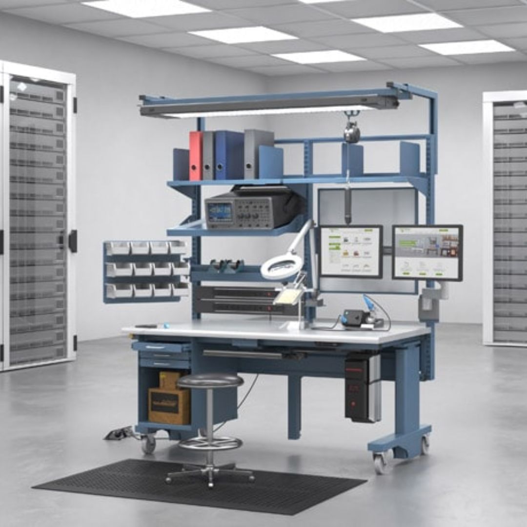
 ESD-Safe WorkbenchesStatic-dissipative workbenches and shelving that ground boards, modules and tooling in line with ANSI/ESD S20.20 practice for electrostatic discharge control.
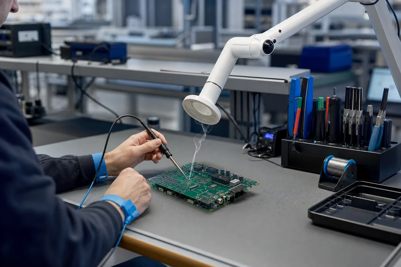 Solder & Fume Extraction at the BenchArticulated extraction arms integrated into the workstation layout so solder fume is captured at the source without disrupting ESD grounding.
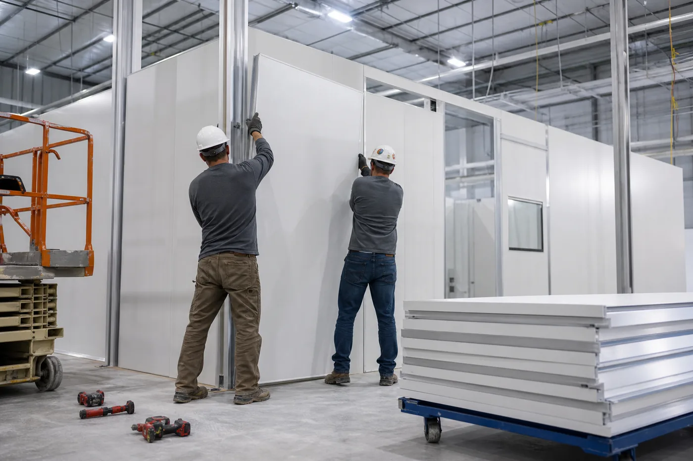 Modular Cleanrooms for Board & Module AssemblyWashable modular cleanroom enclosures where board population, conformal coating or module integration needs particulate control beyond an open shop floor.
 Kitting Stations for Build StagesBin shelving and kitting carts sized to small, high-value components so a build kit is staged complete before it reaches the bench.
Why Static and Contamination Control Drive the Layout
- ESD damage is often invisible: a discharge event can degrade a component without an immediate failure, showing up later as a field return — grounded workstations and storage are cheaper than chasing that failure mode after the fact.
- Kitting accuracy: a missing part discovered mid-build stops the line; bin shelving organized by kit rather than by generic part family cuts that down.
- Documentation: avionics build records often need to show what storage and handling controls were in place — a defined ESD workstation and cleanroom layout supports that record.
Material Handling USA supplies and installs ESD-rated furniture, cleanroom structures and storage systems; we are not a certifying body for ANSI/ESD S20.20 or a substitute for your own quality system.
Planning an ESD-Controlled Line
- Your facility’s existing ESD control plan (ANSI/ESD S20.20 or internal equivalent) — workstation grounding and mat/strap connection points are built to match it, not set independently.
- Component sensitivity classification for the boards or modules you build — drives how strict the grounding and packaging requirements are at each station.
- Kit complexity and number of unique part numbers per build — sets whether bin shelving or a full kitting cart system makes more sense.
- Cleanroom classification target, if any, for board population or coating steps — determines modular cleanroom wall, ceiling and filtration package.
- Throughput and number of parallel build stations — sets how many ESD workstations and kitting carts to spec.
We coordinate directly with your quality or process engineering team so the furniture and cleanroom specification supports the ESD control plan you already have in place.
The Numbers an ESD Workstation Has to Hit
“ESD-safe bench” is a marketing phrase. An electrostatic protected area is defined by measurable resistance values and a verification routine, and those values are published in sources you can read without buying a standard. NASA’s ESD control workmanship handbook, NASA-HDBK-8739.21, and Marshall’s MSFC-RQMT-2918E are both public and mutually consistent with the industry program standard.
| Element | Value | Source |
|---|---|---|
| EPA worksurface (static dissipative) | 1×10⁵ to 1×10⁹ Ω | MSFC-RQMT-2918E; NASA-HDBK-8739.21 default worksurface conductivity |
| Common point ground continuity | ≤1 Ω point-to-point | NASA-HDBK-8739.21 |
| Equipment grounding conductor | <1.0 Ω | ANSI/ESD S20.20-2021, Table 1 |
| Auxiliary ground to equipment grounding conductor | <25 Ω | ANSI/ESD S20.20-2021, Table 1 |
| Equipotential bonding of EPA elements | <1.0×10⁹ Ω | ANSI/ESD S20.20-2021, Table 1 |
| Soft-ground resistor where conductive surfaces are used | >800 kΩ (or GFCI protection) | NASA-HDBK-8739.21 |
| Program applicability thresholds | ≥100 V HBM, ≥200 V CDM; isolated conductors <35 V | ANSI/ESD S20.20-2021 scope |
Two consequences for buying. First, if your build handles Class 0 or Class 1A devices — below those default thresholds — your ESD coordinator will tighten the program beyond these defaults, and the bench specification has to follow. Second, a bench cannot be “certified” to ANSI/ESD S20.20; that standard addresses an organization’s ESD control program. The correct language on a purchase order is that the worksurface and grounding hardware are specified to the resistance limits above — and then that your own verification confirms it in place.
Anatomy of a Compliant Bench
Every part of the station either participates in the ground path or is a liability sitting next to it.
Common point ground and bus bar
One defined ground point per station, with the worksurface, wrist strap, shelf, tool holders and any conductive fixture bonded to it, and the path back to the equipment grounding conductor verified — not assumed from the fact that the outlet has a ground pin.
Worksurface and its mat
Dissipative laminate or mat within the 105–109 Ω window, replaceable, and bonded through a defined resistance rather than metal-to-metal. Conductive worksurfaces need the soft-ground resistor or GFCI protection called out above.
Shelving, uprights and accessories
Overhead shelves, bin rails, light fixtures, monitor arms and drawer units are all part of the EPA if an operator can touch them while holding a device. Each needs to be bonded or verified dissipative, which is exactly why mixing a shop-grade workbench with ESD accessories rarely passes verification.
Insulator discipline
Common process insulators — tape rolls, coffee cups, plastic trays, unlabelled bags, personal items — either come out of the EPA or get separated by distance and handled with ionization. A written exclusion rule is easier to enforce than a judgement call at each bench.
Verification is a cadence, not a purchase. Operator ground checks each shift, plus a periodic program of worksurface and ground measurements with recorded results, is what turns a well-specified bench into evidence.
The EPA Does Not Stop at the Bench Edge
Boards spend more time moving and waiting than they spend under a soldering iron, and most latent damage happens in the gaps. Extending the protected area across the flow means:
- Flooring and seating that participate in the ground path where the program relies on flooring/footwear rather than wrist straps alone.
- Carts and transfer between stations with dissipative surfaces and a defined path, so a board never rides on an unprotected shelf across an aisle.
- Storage shelving inside the EPA — dissipative shelf surfaces and bins, not standard painted steel and standard plastic totes.
- Packaging that stays with the item: shielding bags for transport outside the EPA, dissipative in-plant containers inside it, and one part number per compartment so hardware is never poured between bins.
- Marked EPA boundaries with signage at every entry, because the boundary only works if everyone can see where it is.
Moisture-Sensitive Devices Need Storage, Not a Shelf
Plastic-encapsulated devices absorb ambient moisture, and a device that exceeds its floor life before reflow risks internal cracking and delamination during soldering. That makes dry storage a genuine material-handling requirement on an avionics line, not an afterthought — and the industry practice is well established: track moisture sensitivity level, track exposure time out of the barrier bag, track reflow cycles, and bake or dry-store to reset exposure when limits are approached.
Planning the dry storage is straightforward once you frame it as a queue: how many reels, trays and tubes are open at any moment, how long they sit between kitting and placement, and how many are returned partly used. The chronic failure mode is a single cabinet sized for the average, so partial reels stack on an open shelf during a busy build. The specific floor-life and bake limits belong to the device manufacturer’s data and your process specification — they are never a number we supply.
The same discipline applies to kitting for high-reliability builds. Aerospace electronics is typically built to the highest product class in the industry’s soldering standard, where the requirement is performance on demand for equipment whose downtime cannot be tolerated. Kits for that class need completeness verified before release, lot identity maintained inside the kit, ESD packaging carried in the kit rather than stripped at the window, and a closed, dissipative kit cart so the kit does not become a FOD source between the crib and the line.
Cleanroom or Controlled Environment for PCBA?
Many avionics specs ask for a cleanroom when what the process needs is a controlled environment with defined humidity, temperature and particle behavior. Air cleanliness classes are defined by ISO 14644-1:2015, which covers nine classes across particle sizes from 0.1 to 5 µm. If a legacy document on your desk says “Class 10,000,” it is quoting FED-STD-209E, which was cancelled in November 2001 — restate it in ISO terms before you buy anything against it.
Practically, a modular in-plant room usually gets an assembly area to a genuinely controlled state faster and more flexibly than site construction, and it can move when the line moves. Two honest caveats: a room is designed and built to a class, then demonstrated by testing and monitoring under ISO 14644-2 and -3 by you or a third party — not certified by the supplier — and any enclosed structure still goes to your authority having jurisdiction for review.
Fume extraction deserves its own line here. Solder fume arms, filtration units and downdraft benches all introduce metal ductwork, motors and enclosures into the EPA. Bond them into the same common point ground as the bench, keep the arm’s reach from forcing operators to work outside the protected surface, and confirm the extraction hardware’s own surface resistance rather than assuming it is neutral.
Sources used for this planning guidance
Resistance values above come from the public NASA documents — NASA-HDBK-8739.21 and MSFC-RQMT-2918E — and from the published scope and Table 1 summary of ANSI/ESD S20.20-2021, with cleanroom classes from ISO 14644-1:2015 and soldering product classes from IPC. S20.20 and the IPC standards are paid documents, so we paraphrase rather than reproduce them, and we quote the free NASA sources for the actual numbers. Your ESD coordinator owns the program, the verification records and the decision on tighter limits for sensitive device classes.
Size the Kitting and Parts Storage Before the Benches
Free Parts Kitting & Storage Planner
Enter your part-number count, kits per shift, container sizes and available footprint, and the planner works out the storage mix and staging space a kitting operation of that size needs — results on screen before it asks for anything. On an avionics line it answers the question that usually gets decided by guesswork: how many locations the crib really needs, and how much staging the line requires so kits are not parked on the floor beside the benches.
Plan my kitting area See parts storage & kitting systems
For the benches themselves, send your device class, station count and bench lengths with a quote request and we will specify worksurface, grounding hardware and shelving against the limits in the table above.
Get a free quote
Tell us what you are storing, the room size and your timeline. A project specialist will follow up with layout options and pricing. Prefer to talk? Call (800) 326-4403.
Common Questions
What makes a workbench ESD-safe?
Do you supply cleanrooms for electronics assembly?
Can kitting stations be reconfigured as product mix changes?
Is this different from a general electronics manufacturing storage setup?
Explore Related Storage Systems
 Aerospace & Defense Parts Storage — StoreganizerHigh-density pocket shelving for small, high-value aerospace and defense components.
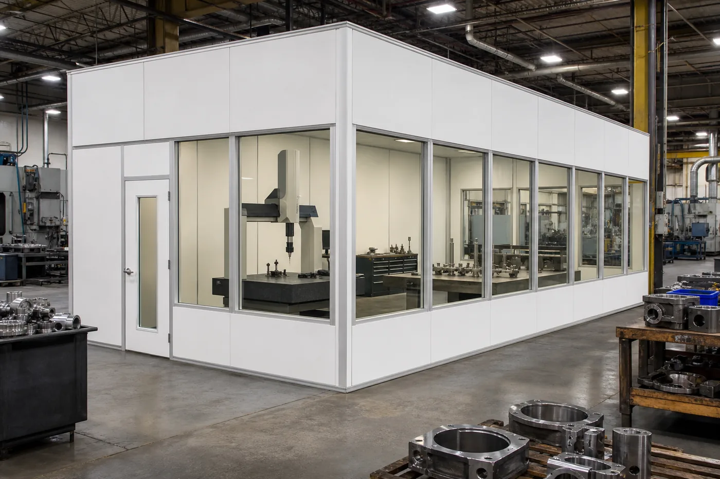 Aerospace Material Handling Solutions HubBack to the full range of aerospace storage systems, compliance context and audience-specific guidance.
Ready to Lay Out Your ESD Line?
Tell us your build volume and component sensitivity — we will spec the workstation, cleanroom and kitting mix that fits your process, free of charge.