
Anatomy of a Mobile Shelving System: Parts, Components and How They Work
Rail, carriage frame, drive mechanism, end panel, shelf deck — the terms sound simple until you’re reading a spec sheet. Here is what each part of a mobile shelving system is, and how they work together.
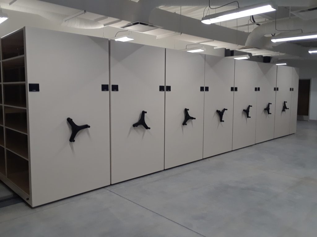
Rail
Fixed to the floor; guides every carriage in the run
Carriage
The moving frame + wheels every housing sits on
End panel
Carries the drive control — one per carriage front
Drive train
Handwheel or motor → reducer → shaft → wheels
The same handful of parts, on every mobile shelving system
Manufacturers describe their systems with different marketing names, but underneath, every track-mounted mobile shelving system is built from the same short list of parts: a rail fixed to the floor, a moving carriage on wheels, an end panel with a drive control, a drive mechanism that turns the wheels, and a shelf deck or other housing carried on top. Knowing these terms makes it possible to read a spec sheet, compare two manufacturers’ products, or describe a problem to a service technician accurately.
This page names each part, explains what it does, and links out to the pages on this site that cover each part’s design choices in depth — rail type, drive type, deck type and safety hardware — rather than repeating that detail here. If you are planning how much future capacity to build in, see designing a system for future expansion.
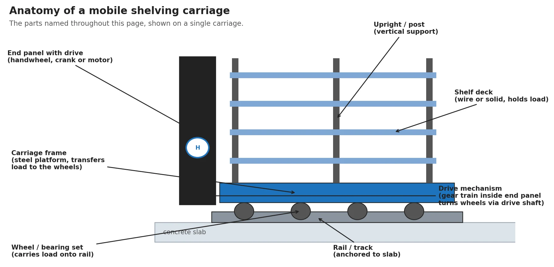
The carriage: the part that moves
The carriage is the steel platform that rolls on the rail. Everything stored in the system sits on a carriage, and every carriage moves independently, which is what lets a mobile system compress the aisles down to one open aisle instead of one aisle per unit.
Multiple carriages sit side by side on the same rail run, with one open aisle that moves as carriages are driven apart. The number of carriages, their depth and their height are all decided during the system’s initial sizing — see the capacity and sizing calculation guide.
Rail and track: what the carriage rides on
The rail (also called the track) is fixed to the floor and runs the length of the carriage row. Every carriage’s wheels engage this rail, which keeps the whole run moving in a straight line and, on systems with a guidance feature, keeps carriages square to each other as they move.
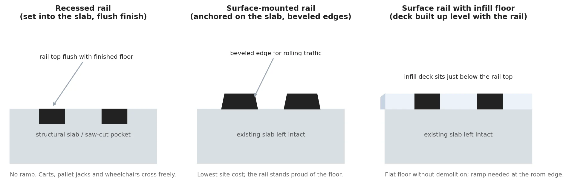
Recessed or surface-mounted
Rail is installed one of two ways: recessed into a shallow trench so the floor is flush on both sides, or surface-mounted with a ramped transition up to the rail height. Recessed rail is more common in new construction, since the floor can be prepared for it; surface-mounted rail is the practical answer for existing buildings and retrofits where cutting the slab is not an option. Neither choice changes what the rail does mechanically — it is purely a floor-preparation and accessibility decision, covered in full in recessed vs. surface-mounted rail.
Whichever type is used, the rail has to be anchored to a floor that can carry the loaded system — see floor load requirements before assuming any floor is ready for rail installation.
The drive mechanism: how the carriage actually moves
The drive mechanism is the set of parts between the operator’s input (or a motor) and the wheels turning. On a mechanical-assist carriage, the sequence is straightforward and mechanical the whole way through:
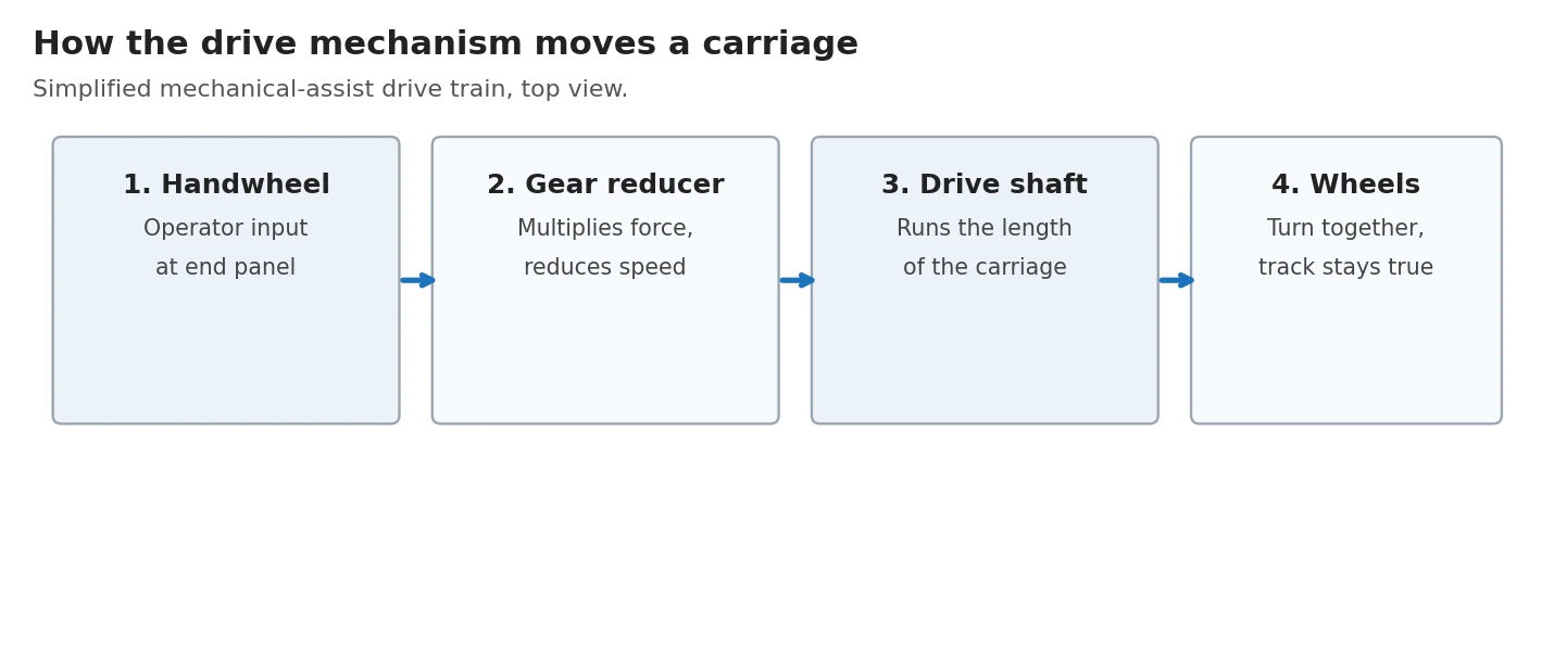
- Handwheel — the operator’s input point, mounted on the end panel.
- Gear reducer — multiplies the operator’s turning force and reduces the speed, which is why a heavily loaded carriage still moves with light effort at the handwheel.
- Drive shaft — runs the length of the carriage, transferring rotation from the gear reducer to the wheels.
- Wheels — turn together so the carriage tracks straight along the rail instead of skewing.
A manual carriage skips the gear reducer and drive shaft entirely — the operator pushes the carriage directly. A powered carriage replaces the handwheel with an electric motor and adds a control circuit, but the gear reducer, drive shaft and wheel arrangement downstream of the motor work the same way. The choice between these three drive types is a separate decision covered fully in manual vs. mechanical-assist vs. powered mobile shelving, including how it affects operating force, cost and future control-system capacity.

The end panel: one control point per carriage
The end panel is the finished face at the aisle end of each carriage — the surface people actually see and use when they open an aisle. It carries the drive control (handwheel, crank or motor button/keypad), usually a label holder identifying the carriage’s contents, and on many systems, an integrated lock or interlock for security and safety.
Reading a mobile shelving spec sheet or quote?
Send it to us and we will walk through the terminology — rail type, drive type, deck type and safety hardware — so you know exactly what you are comparing.
Because one drive mechanism moves the entire carriage, only one control point is needed per carriage front — typically centered on the end panel at a comfortable operating height. A carriage with controls anywhere else (the long side, the back, or multiple points on one front) is not a normal configuration and usually indicates either a misidentified part or a non-standard installation.
The end panel is also where finish and material get chosen — see finish, material and end-panel options for powder-coat, laminate and corrosion-resistance considerations.
Shelf decks and other housings
The shelf deck is the surface that items actually sit on, mounted between the uprights at each level. Not every carriage carries plain shelving — the same carriage frame can carry filing units, flat-file drawers, lockers or other housings, but shelving is the most common.

Decks are generally either wire (open grid, better airflow and visibility, lighter) or solid (flat pan, better for small or irregular items, easier to clean). The choice affects airflow, visible dust accumulation and how items are contained on the shelf, and is covered fully in wire vs. solid shelf decks.
Safety hardware: the parts that prevent injury and damage
Beyond the parts that make the carriage move, several components exist specifically to prevent a moving carriage from causing harm.
| Component | What it does |
|---|---|
| End stops | Physically limit how far a carriage can travel at each end of the rail |
| Aisle lock | Holds a carriage in place so it cannot be moved while an aisle is in use, on some systems as a manual pin or lever |
| Base sensor / sweep guard | On mechanical-assist and powered systems, detects an obstruction at floor level and stops the carriage before it closes |
| Access control / interlock | Restricts who can move which carriage, from a simple key lock to an electronic access system |
| Anti-tip provisions | Structural or mechanical features that keep a heavily loaded carriage stable, especially relevant where any housing (such as a drawer) can extend and shift the load |
Which of these a given system needs depends heavily on drive type, occupancy and the material being stored. The full selection guide is in mobile shelving safety features and design, and who is authorized to operate which carriage is covered in security and access control.
Quick-reference glossary
| Term | Definition |
|---|---|
| Carriage | The moving platform (frame + wheels) that a mobile shelving unit’s shelving or other housing is mounted on |
| Rail / track | The fixed steel guide the carriage’s wheels ride on |
| Carriage frame | The structural steel base of the carriage |
| Upright / post | A vertical support column on the carriage that holds the shelf decks |
| Shelf deck | The wire or solid surface items sit on, mounted between uprights |
| End panel | The finished aisle-facing surface of a carriage, carrying the drive control |
| Handwheel | The manual input point on a mechanical-assist carriage’s end panel |
| Gear reducer | Mechanism that multiplies force and reduces speed between the handwheel and the drive shaft |
| Drive shaft | Shaft running the length of the carriage that transmits rotation to the wheels |
| End stop | Hardware limiting carriage travel at the end of the rail |
| Aisle lock | Hardware that holds a carriage in place, preventing movement while an aisle is open |
| Base sensor / sweep guard | Obstruction-detection hardware at floor level on mechanical-assist/powered systems |
For terminology specific to specifying and bidding a project — submittals, cut sheets and review steps — see the specification and submittal checklist.
Frequently asked questions
What is a carriage in a mobile shelving system?
What is the difference between the rail and the track?
What actually moves the carriage — the handwheel, a motor, or something else?
Why does each carriage front only have one handle?
What stops a carriage from tipping or crushing something in the aisle?
What is the difference between the shelf deck and the carriage frame?
Do these parts need regular maintenance?
Get help matching parts to your project
Send us your space, your collection and any spec sheet you’re comparing. We will walk through the rail, drive, deck and safety options and recommend a system that fits.